- 您现在的位置:买卖IC网 > Sheet目录324 > FAN3121CMPX (Fairchild Semiconductor)IC GATE DVR SGL 9A LOSIDE 8-MLP
Typical Performance Characteristics
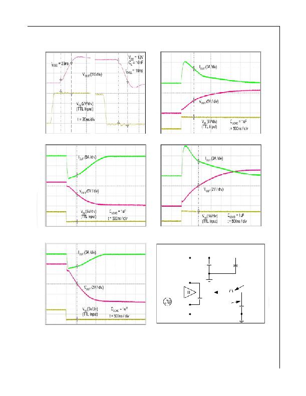
Typical characteristics are provided at 25°C and V DD =12 V unless otherwise noted.
Figure 40. Rise / Fall Waveforms with 10 nF Load
Figure 42. Quasi-Static Sink Current with V DD =12 V (15)
Figure 41. Quasi-Static Source Current with V DD =12V
Figure 43. Quasi-Static Source Current with
V DD =8 V (15)
V DD
(2) x 4.7μF
470μF
ceramic
Al. El.
(15)
FAN3121/22
Current Probe
LECROY AP015
IN
1kHz
1μF
ceramic
I OUT
V OUT
C LOAD
1μF
Figure 44. Quasi-Static Sink Current with V DD =8 V (15)
Figure 45. Quasi-Static I OUT / V OUT Test Circuit
Notes:
14. For any inverting inputs pulled LOW, non-inverting inputs pulled HIGH, or outputs driven HIGH; static I DD
increases by the current flowing through the corresponding pull-up/down resistor, shown in Figure 7.
15. The initial spike in each current waveform is a measurement artifact caused by the stray inductance of the
current-measurement loop.
? 2008 Fairchild Semiconductor Corporation
FAN3121 / FAN3122 ? Rev. 1.0.3
13
www.fairchildsemi.com
发布紧急采购,3分钟左右您将得到回复。
相关PDF资料
FAN3213TMX
IC GATE DRIVER DUAL 4A 8-SOIC
FAN3217TMX
IC GATE DRIVER DUAL 2A 8-SOIC
FAN3223CMX
IC GATE DVR DUAL INV 4A 8-SOIC
FAN3226CMPX
IC GATE DVR DUAL 2A 8-MLP
FAN3227TMPX
IC GATE DVR DUAL 2A 8-MLP
FAN3268TMX
IC BRIDGE DVR P/N-CH 2A 8SOIC
FAN3278TMX
IC BRIDGE DVR P-N 2A 30V 8-SOIC
FAN5331SX
IC LED DRVR WHITE BCKLGT SOT23-5
相关代理商/技术参数
FAN3121CMX
功能描述:功率驱动器IC Single 9A High Speed Low Side Gate RoHS:否 制造商:Micrel 产品:MOSFET Gate Drivers 类型:Low Cost High or Low Side MOSFET Driver 上升时间: 下降时间: 电源电压-最大:30 V 电源电压-最小:2.75 V 电源电流: 最大功率耗散: 最大工作温度:+ 85 C 安装风格:SMD/SMT 封装 / 箱体:SOIC-8 封装:Tube
FAN3121CMX_F085
制造商:FAIRCHILD 制造商全称:Fairchild Semiconductor 功能描述:Single 9-A High-Speed, Low-Side Gate Driver
FAN3121CMX_F085_12
制造商:FAIRCHILD 制造商全称:Fairchild Semiconductor 功能描述:Single 9A High-Speed, Low-Side Gate Driver
FAN3121T
制造商:FAIRCHILD 制造商全称:Fairchild Semiconductor 功能描述:30V PMOS-NMOS Bridge Driver
FAN3121TMPX
功能描述:功率驱动器IC Single 9A High-Speed Low-Side Gate RoHS:否 制造商:Micrel 产品:MOSFET Gate Drivers 类型:Low Cost High or Low Side MOSFET Driver 上升时间: 下降时间: 电源电压-最大:30 V 电源电压-最小:2.75 V 电源电流: 最大功率耗散: 最大工作温度:+ 85 C 安装风格:SMD/SMT 封装 / 箱体:SOIC-8 封装:Tube
FAN3121TMX
功能描述:功率驱动器IC Single 9A High-Speed Low-Side Gate RoHS:否 制造商:Micrel 产品:MOSFET Gate Drivers 类型:Low Cost High or Low Side MOSFET Driver 上升时间: 下降时间: 电源电压-最大:30 V 电源电压-最小:2.75 V 电源电流: 最大功率耗散: 最大工作温度:+ 85 C 安装风格:SMD/SMT 封装 / 箱体:SOIC-8 封装:Tube
FAN3121TMX_F085
制造商:FAIRCHILD 制造商全称:Fairchild Semiconductor 功能描述:Single 9-A High-Speed, Low-Side Gate Driver
FAN3121TMX_F085_12
制造商:FAIRCHILD 制造商全称:Fairchild Semiconductor 功能描述:Single 9A High-Speed, Low-Side Gate Driver
